Terms And Conditions Please Read and Accept the Daytona Drone Club Terms to participate in the Forum
The build progress
Kore carrier board yellow cube
40a hobbywing esc
brother hobby r7 4008-490kv motors
13in 3 blade props
6s battery to start
telemetry holybro v3 500mw
radio tx16s with ?? trying frsky r xsr
Have moved into the software phase.
open tx, mission planner, qground control
hit a big wall issues getting the reciever working with the radio, Gps here3 not nowhere near working, had it then lost it. Getting tones but wont arm--lucky for me. Still a while to go to figure out mission planner setup
The spekworks kore carrier board has limited information or at least I cant find it yet. The mission continues

Research for future calibration if I ever get there
Setting up the Battery voltage sensor
The 200A Hall Effect sensor needs to be calibrated at 0A to get correct readings. The parameters in documentation are based on an average from the sensor’s manufacturer, which is “good enough” for casual use. But if you’d like to calibrate it to get more accurate readings about the zero point, follow these instructions. This calibration should only ever need to be done once per board:
-
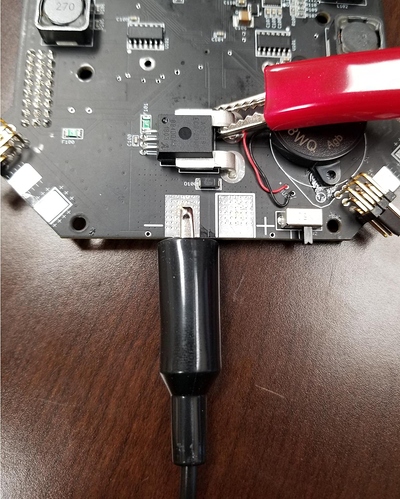
Using a bench-top power supply or a battery, use alligator clips to connect the positive wire to the in-board bus bar of the current sensor. This will energize the entire board, but bypass current through the current sensor. This way, you can get a true 0A reading.
-
Power up the board in this configuration and connect to Mission Planner. Set the following parameters to these temporary values:
BATT_AMP_OFFSET = 0
BATT_AMP_PERVOLT = 1

Doing this will cause Mission Planner to report the direct analog voltage it is reading from the current sensor.
-
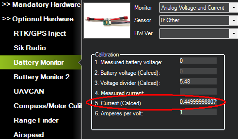
Go to Initial Setup -> Optional Hardware -> Battery Monitor. In the calibration box, read the value for “Current (Calced)”. That is your offset voltage at 0A.
-
Set the offset parameter to the value you read in#3:
BATT_AMP_OFFSET = [value]
BATT_AMP_PERVOLT = 50 -
Power down and reattach the positive cable to the main solder pad. Your current offset voltage should now be calibrated.
Calibrating the 0A offset removes most of the error from the current readings. If you require the full accuracy that the current sensor offers, you will also need to calibrate the BATT_AMP_PERVOLT parameter. I don’t recommend doing this unless you are familiar with high-power electronics. For most users, a value of 50 is good enough.
You will need an accurate external load of some kind, such as a programmable artificial load or precision power resistors. Attach the load to the ESC power pads and back-calculate the multiplier based on the equation of a line. Set the OFFSET and PERVOLT parameters to 0 and 1 (same as step #2 in previous post) so you can read the direct analog voltage in Mission Planner.
Representing the equation of a line as y = mx+b:
y = the current in Amps (this should be known based on your external load)
m = BATT_AMP_PERVOLT
x = analog voltage from sensor
b = BATT_AMP_OFFSET
You can solve for m, as you will know all of the other values. I recommend you choose at least 2 current values and take the average result.
Radio Receiver setup attempt #2 This is attempt #2 tried to setup FrSky and failed
I had a couple receivers (nano) hanging around so here we go
(posted)
Team Black Sheep RC Systems
Any Crossfire compatible receiver can be used with ArduPilot.
(This is the intent to begin with, basic radio controller input)
If you do not wish to use telemetry then a TBS Crossfire receiver can be connected to the RCIN port using SBUS
In the configuration of the serial port select the RCIN protocol. So for example for serial port 4:
- Set SERIAL4_PROTOCOL = 23
- Set RSSI_TYPE = 3
With the receiver connected and configured correctly proceed with RC calibration as normal.
(setup Later)
If you wish to use telemetry then a TBS receiver can be connected to a UART utilizing the CRSF protocol.
CRSF is a full-duplex protocol that supports integrated telemetry and a number of other features. Connect the RX pin of the UART to the TX pin of the CRSF device and vice versa. Currently a full-duplex UART connection is required.
Summary: there are 2 firmwares that get flashed to the cube. PX4 or ardupilot At this point I am using px4 because it configures the remote radio, the ardupilot requires input channels to be setup it says. Either way learning the configuration points of either is pretty difficult and I am trying to advance without getting stuck for days. And it happens, that's because this is all new learning and to be honest resourses are scattered and reading forums that have user posts are without direction and a real time waster.
(update) after a couple days of reflashing firmware and settings update the ardupilot ChibiOS the radio control is working with this also
Status:
Radio tx16s connected and shows up in mission planner (sometimes depending on the firmware)
At least there is an answer to how to setup an independent radio control channel. There are instructions about setting up the tx16s with the telemetry setup but all I wanted to do was have the ability to control the drone by the handheld alone'
Made some progress with the crsf. The install to Kore carrier board is


+ just to be clear on the KORE the outside wire is ground, then positive then the signal The orange wire on the receiver is the TBS ground, followed by the positive , then the signal
yes stupid using 2 yellow wire but sometimes at 1am it's just about making the connection.
The photo shows the #3 wire yellow going to the signal pin (s) on the PPM row, the #4 wire not connected yet
This allows for control to show up in mission planner sometimes, depends on the firmware so far px4 yes -ardupilot no , not completely sure yet
Win one, lose a couple days because hardware and software just not ready for prime time (piece of crap here3 GPS)
Here3 Summary: Canbus not working with either firmware
Been changing the firmware trying to figure out why the can bus is not talking to the here3 antenna, I am starting to think the here3 is not working and thats another mission that was failed. Trying to talk to the chip inside using the instructions also fail
Status: Radio connection sometimes, calibration of compass took 24hours of whatever, fortunately I have a mini carrier board I was able to use to help troubleshooting. Trying to position the quad for the setup sucked but putting the cube in the small carrier was a breeze, I was finally able to get the 100 percent cal but it took 35 tries
Obliviously what is happening is I am learning the programs and the terminology
the holybro telemetry is hooked up and working, how I just dont know at this point
The radio is setup output 1 in nano config is SBUS

starting point instruction that's watchable 2:30 timeline
Here3 gps overall not worth the trouble and definately not worth 125 bucks
I abandoned the canbus and was able to wire up the here 3 in i2c mode. disassembly allows changing the cable and a selector switch to change modes
The px4 firmware finds the gps but not the compass
Summary:
Will be looking for a better GPS antenna and try to figure out can bus. Am able to move forward, radio check good, sensors good, push armed saftey switch operating
Next step getting motors spinning. radio control says communication but no motor movement
Kore Carrier wiring has option to power the esc, jumper connection is made so wiring must be suspect
It appears the telemetry is the next to get addressed so here goes
I spent the past week working with and trying to understand the telemetry system. Mavlink and a pair of junk Holybro telemetry radios. With that time waisted I just decided that purchasing a real system had to be done, not some thousand dollar rigs but the ones made by the Australians.
Plugged them in and they just started humming, because I had to take on another concept in drones i started building the Daytona Drone racer. After a small fire and a couple burnt up electronic boards I made some progress there so it was back to the big build ser #1 to punish my brain some more. I am still having problems with the radio controller radio link, I decided to use the tx16s radio for both builds and crsf nano on both. Of course the small drone uses betaflight and it configures on way then the large drone uses mission planner and that's a pretty difficult concept also. Back to the radio issue, both rigs show radio connection when plugged into the computer but when the computer link is removed and it's just radio waves neither can spin up the motors. I plan on a couple hours to shake out this radio so I can remove the tether of the cable
With that this is the progress, the cube/kore is sending commands to the esc's and the motors are spinning. I had to do advanced configuration in mission planner to get the motors in the right sequence and in the right direction but at least I made some progress. A couple setbacks with the racer, small fire and lost parts but the learning continues