Terms And Conditions Please Read and Accept the Daytona Drone Club Terms to participate in the Forum
The disclaimer here is This is a Brand New project being build first time with limited experience with the nomenclature, Terms used, and technologies. Basics will be covered and hopefully explained for new builder
When I take on a new project I expect to have to learn new terms and concepts. Starting out with this pixhawk 4 I figured this would be well documented and a lot of information to help with a smooth build.
so far because I have had a terrible experience with here3 and canbus i had hoped this complete kit would be a breeze, it comes with all the components and the power distribution board.
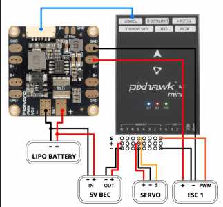
So the first thing i encounter hooking up the ESC to the power board is plugging in the signal to the esc. there is a picture but the explanation is written in complete tec jargon check this
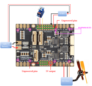
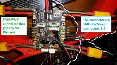
Depending on your airframe type, refer to Airframe Reference to connect I/O PWM OUT and FMU PWM OUT ports of Pixhawk 4 to PM board. MAIN outputs in PX4 firmware map to I/O PWM OUT port of Pixhawk 4 whereas AUX outputs map to FMU PWM OUT of Pixhawk 4. For example, MAIN1 maps to IO_CH1 pin of I/O PWM OUT and AUX1 maps to FMU_CH1 pin of FMU PWM OUT. FMU PWM-IN of PM board is internally connected to FMU PWM-OUT, which is used to drive servos (e.g. aileron, elevator, rudder, elevon, gear, flaps, gimbal, steering). I/O PWM-IN of PM board is internally connected to M1-8, which is used to drive motors (e.g. throttle in Plane, VTOL and Rover).
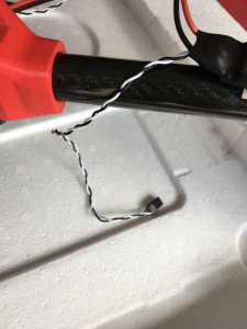
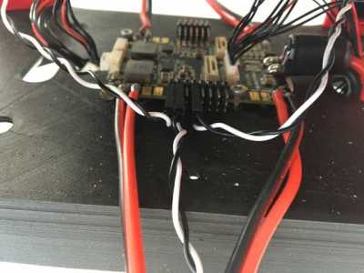
Ok so where in the hell does the black and white wire from the esc go? Why can't there just be some simple pictures , there are 3 wires out one side and 4 on the other
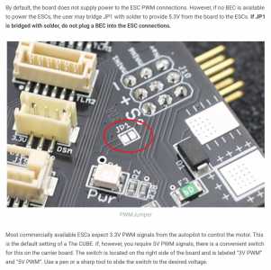
I will assume the power board will be able to control the esc. one of the issues i ran into with the spekworks Kore board was the need to solder the j1 jumper to provide power to the pwm outputs
Kore Board some additional information here that could help, I made the jp1 connection and the board controls the esc and the motors spin
Why would they make this note.
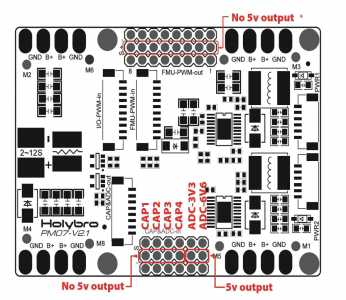
Note that the PMB does not supply power to the
servos via + and - pins of FMU PWM-OUT. The size of the motor ESC wire, no way could the PWM out provide that power
YEAH look what I found
